

A set of drawings or plans, are used to communicate how a building is to be constructed, showing all relevant information that will be required to do so. This also includes things such as location of the building on the site.
Initial plans are usually for planning purposes, often called Town Planning Drawings. Town Planning drawings are basic in the information shown, and usually only show enough information to demonstrate that the propsed building design and setbacks meet planning requirements.
Once Town Planning Drawings are approved by council, the next stage is to give more detailed information of how the building is to be constructed, often called Construction Documentation referring to the stage the drawings are at. These are the drawings used for building the house.
Types of Common Drawings Typicaly used for building a house:
TITLE PAGE (not always included)
GENERAL NOTES (sometimes included on the title page or site plan, can also be in a specification instead)
SITE PLAN
FLOOR PLAN(s)
ROOF PLAN
ELEVATIONS
SECTION(s)
SHADOW DIAGRAMS
Below are other drawings that are sometimes included in a drawing set to form Building Plans, but are not always required:
INTERNAL ELEVATIONS
REFLECTED CEILING PLAN(s)
POWER PLAN(s) (sometimes also shown on the reflected ceiling plan(s))
DOOR & WINDOW SCHEDULE
LANDSCAPE PLAN (usually drawn by a specialist such as a Landscape Architect)
JOINERY DRAWINGS
DETAILS
Title Page
If included in a drawing set, it is the first drawing you will find (although not technically a drawing as such)
A Title Page lists a table / schedule, of all the drawings included in the building plans drawing set. It is a great reference to be able to find the drawings you need quickly, just like the index/contents page of a book.
The main text shown predominantly on the Title Page is the Site Adress of the project.
It also shows as a part of the table / schedule, the Drawing Number, The Drawing Title and the Scale at which the drawing is plotted at.
Title Pages can sometimes also show 'General Notes' related to the construction of the house. General Notes outline certain requirements expected in the contruction of the home. Often the notes can be a sperate A4 document that is
called a specification. Specifications are usually a lot more detailed in there scope than General Notes.
Here is an example of a simple Title Page.
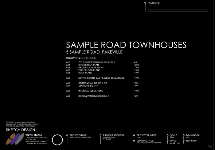
With this page, there is usually no scale as there are no drawings.
A North point direction is not required to be shown either
Site Plan / Setout Plan
Usually the first drawing in a set of drawing plans (unless there is a title page).
What is a Site Plan?
Site plans show a 2D Plan view of the proposed building / alterations / additions in regards to the Site Boundary.
This is important so the building works are correctly located on the site, and also ensures the building siting complies with Building Regulations in regards to Neighbouring Buildings.
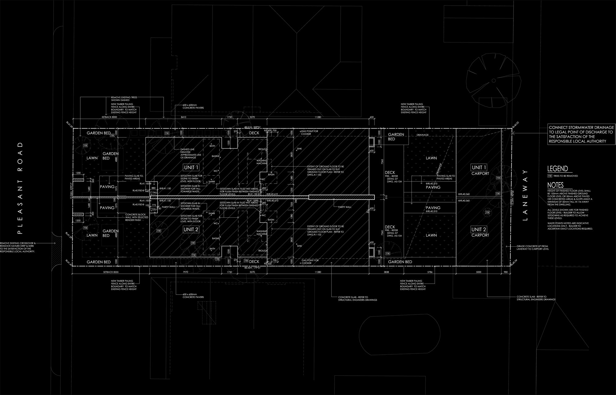
Site plans need to show the title boundary, building envelope, its setbacks from the boundaries, street name, footpath (if applicable), crossovers (including removal of existing ones and location of new ones), legal point of discharge, vegetation (e.g existing large trees to remain and be removed), driveways, neighbouring buildings, site levels/contours and North point direction.
They can also serve as a landscape plan, showing lawn areas, garden beds and paved areas. Sometimes they show the roof plan on the site plan rather than having a seperate drawing of the roof plan.
The information shown on a Site Plan can vary greatly. Some Site Plans show the bare minimum, and some show concrete slab set-backs, set-downs, plumbing locations. Those types of things though can be drawn as a seperate drawing if desired/required rather than put on the Site Plan.
Some Site Plans can also have General Notes listed on the drawing.
Here is an example of a Site Plan. (click image for larger view) (Title Block ommitted in this drawing)
Floor Plan(s)
Floor Plan drawing(s) usually follow after the Site Plan in the drawing set.
What is a Floor Plan?
Floor plans show a 2D Plan view of the proposed building / alterations / additions layout with more detailed information related to the actual building than that shown on a Site Plan.
They are typically at a scale of 1:100 or 1:50
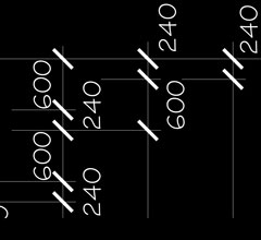
They are heavily dimensioned showing the lengths and thicknesses of walls, door openings and window openings.
Below is a list of items that should be shown on the floor plans.
| Dimensions: Floor plans need to be clearly dimensioned so the house can be built accuratley. Wall thicknesses must be shown so the builder knows what type of wall is to be constructed. All internal dimensions between stud walls should be measured from stud wall face to stud wall face, not from the plasterboard or other finish. In house building plans, you should never measure from plasterboard to plasterboard. |
 |
| Room Names: All rooms should be labelled as to what they are (e.g Bedroom, Laundry etc.). |
|
| Smoke detectors: Locations must be shown to ensure they comply with the BCA / NCC. A simple symbol that represents the Smoke Detector will suffice. |
 |
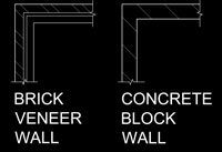
| Wall Types: In terms of drafting, all wall types should be drawn to comply with drafting standards (e.g Brick Walls should have 45 degree angled double lines used to represent them) |
 |
| Notation: All relevant notation to any should also be shown to describe objects that may not be clearly understood from the floor plans alone. |
 |
| Sanitary Items: All baths, showers, sinks, basins, tubs, toilets etc. must be shown so plumbing can be designed for the building and to ensure BCA / NCC compliance. |
|
Doors and Windows: It is also a good idea to place text parrallel to a door indicating its width |
 |
| Joinery: All joinery items should be shown (e.g Kitchen cupboards, Laundry cupboard) |
|
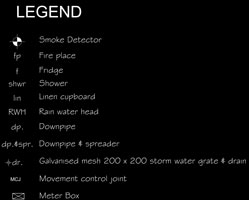
| Legend: A legend is a table on the drawing somewhere that indicates what certain abbreviations on the floor plans mean, or what symbols on the drawings represent. (e.g You might notate AJ on brickwork to mean Articulation Joint) |
 |
| Floor Finishes: It is a good idea to indicate floor finishes for each area of the house if not listed in a specification. This can be done by writing the type of finish below the Room Name or by using codes that are referenced in a Finishes Schedule Legend on the drawing. |
|
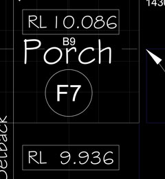
| R.L's: These are important to indicate the levels of the floor above ground level, and on houses with steps, stairs, more that 1 story high and split level. Information you may have from a Land Surveyors drawing should also be incorporated onto the drawing where relevant although a lot of this information will usually be shown on the Site Plan. |
 |
| Downpipes: Down Pipes from the gutters above should be shown to ensure they are not placed in front of doors or windows or interfere with the aesthetics of the building. Downpipe can be simply shown as a circle with the text 'dp' next to it. |
 |
| Appliances: Ovens, cooktops and dishwasher locations should be clearly shown as well as location for refrigerator. Washing machine and drier locations should also be shown. |
|
| General Items: Items such as outside tap locations often are not shown but are a good idea to indicate exact locations. Clothes lines location is another item often not shown on plans but is something to think about and decide on its best location. Indicate the mail box location. |
|
| Services: Always show the location of the Electrical Meter Box and the Gas Meter. If the switch board is not incorporated on the Electrical Meter Box, also show that location. Hot Water Service location should also be shown as well as any water tanks to be connected to the toilet cistern. |
|
| Structual: If you receive drawings from a Structural Engineer, it is good to show the location of columns and give them the same number as per the Structural Engineers drawings. |
 |
| Symbols: On the floor plans Section Lines should be shown to indicate where the section through the building is being taken. Other symbols may refer parts of the floor plan to more detailed drawings. |
Here is an example of a floor plan. (click for larger view) (Title Block ommitted)
Ground floor only shown, not the first floor.

Roof Plan
What is a Roof Plan?
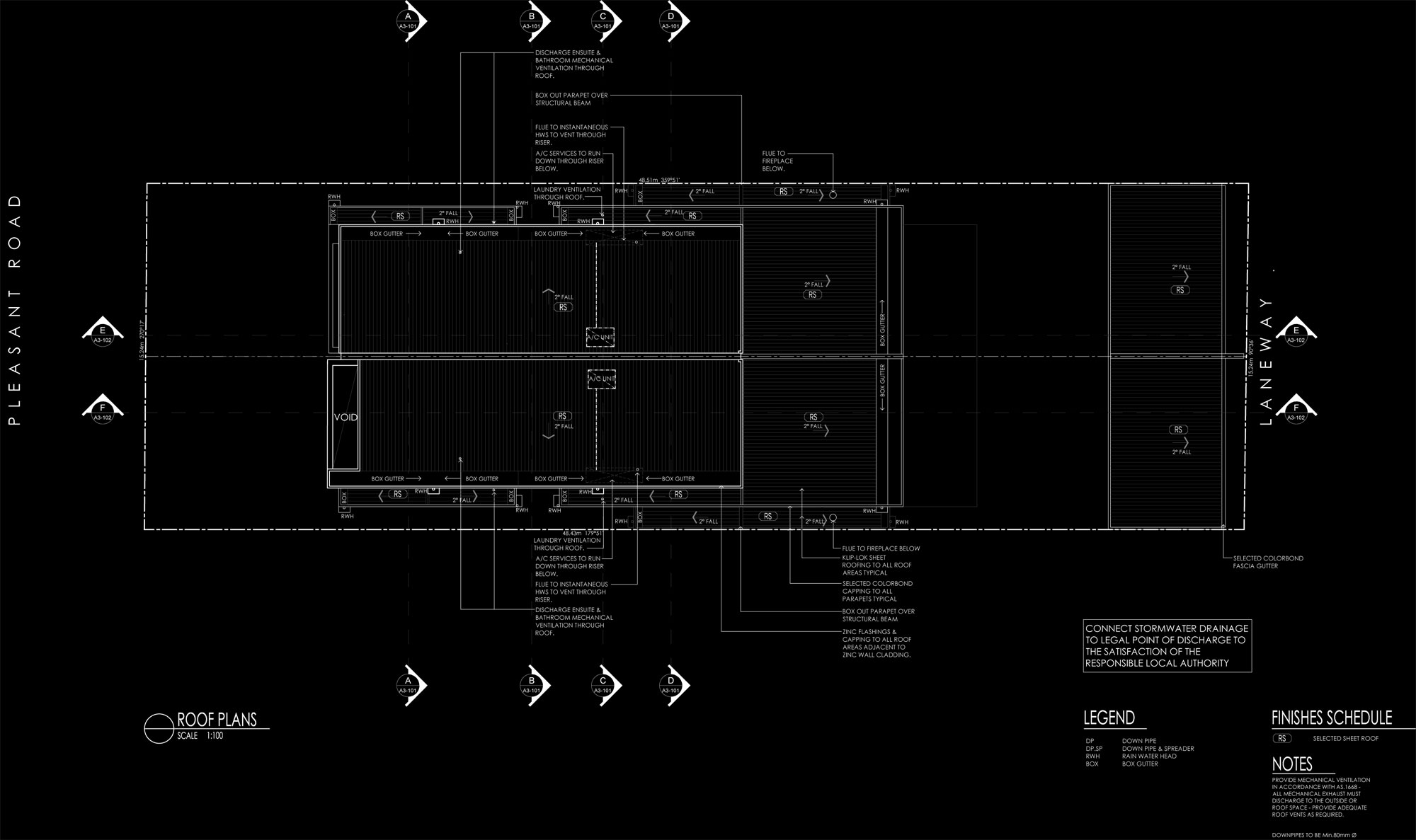
Roof plans show a 2D Plan view of the proposed building / alterations / additions of the entire roof from above the building. Sometimes Roof Plans are not used where it is possible to show the roof lines over the floor plan itself (e.g such as a hip and valley roof, not really an option for flat/skillion roofs.)
They are typically at a scale of 1:100 or 1:50
Roof plans show what the design of the roof will look like, the direction of the fall, eave and box gutters, down pipes, rain water heads, spreaders, the pitch of the roof, skylights, a/c units, flues and the roof material.
Here is an example of a roof plan. (click for larger view) (Title Block ommitted)
Elevations
Generally after the floor and roof plan are the Elevations.
What is an Elevation?
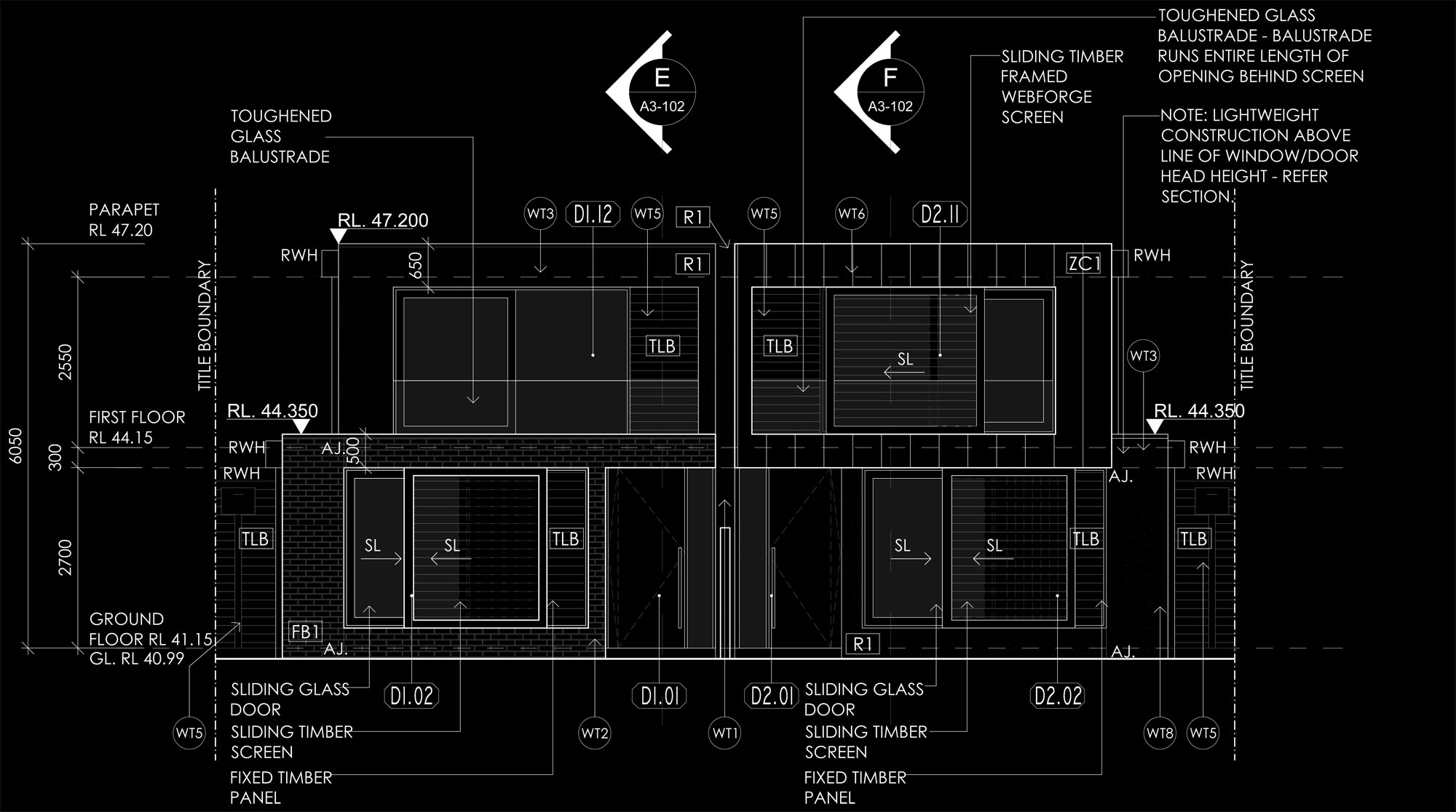
Elevations are 2D views of the sides of the building as if looking at the building exactly side on. They show what the look of the building would be if standing outside of it.
They are typically at a scale of 1:100
Elevations show the material finishes of the building from the outside (exterior), floor to ceiling heights, overall building height, RL's, Door and Window Numbers (as per the floor plans), boundary lines (where applicable) and notation to clarify areas that may not be clear or could be overlooked. It is also good practice to show the location of down pipes and rain water heads, as well as where the section lines pass through.
Here is an example of an Elevation. (click for larger view) (Title Block ommitted)
Sections
Generally after the Elevations are the Sections.
What is a Section?
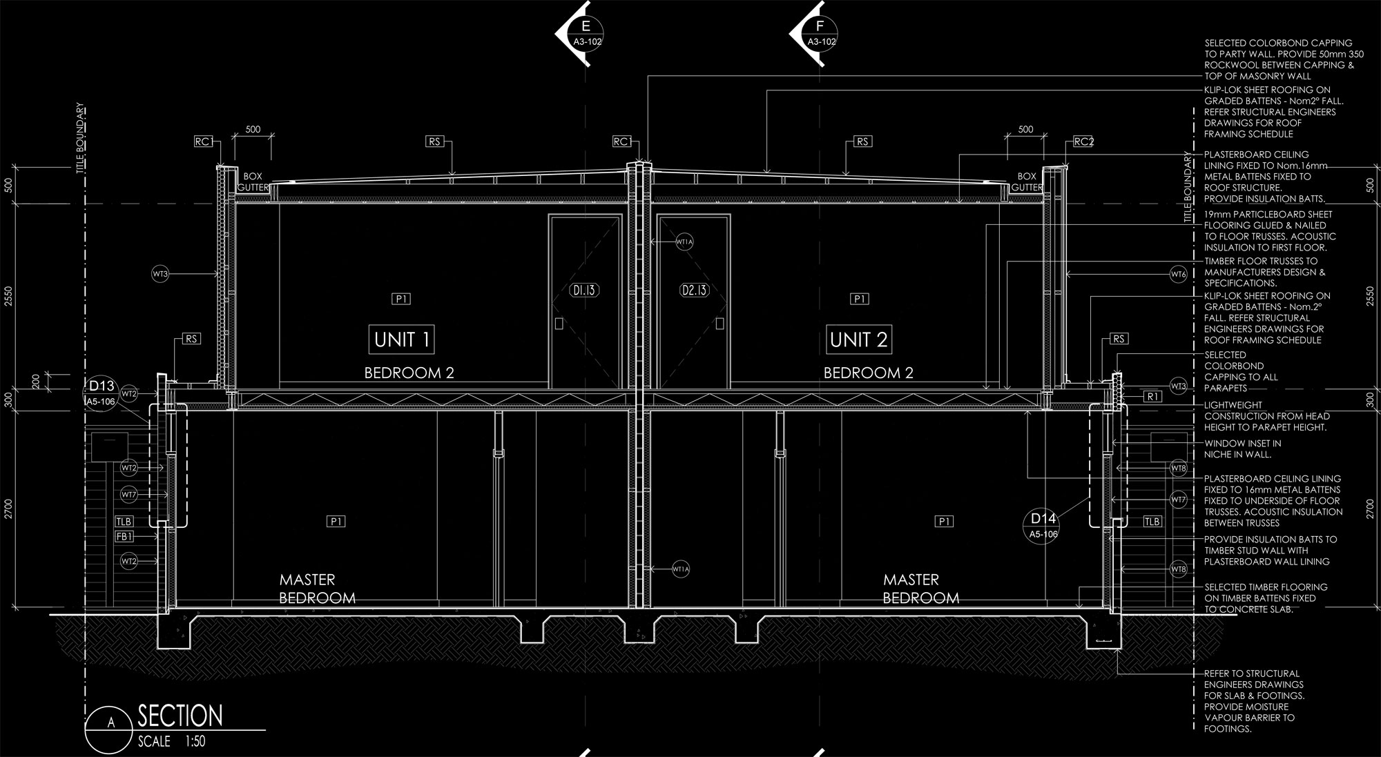
Sections are 2D views through a building as if cutting directly through it to see how it is to be constructed.
They are typically at a scale of 1:50 (sometimes 1:100)
Sections need to specify the materials used for construction and show all structural members throughout that section of the building.
The main areas are:
Subfloor - what the building floor is made of that is sitting on the ground or above the ground - either a concrete slab or bearers and joists. If a bearer and joist floor, the flooring material must also be specified (e.g 19mm particle board sheet flooring.)
All notation to do with the size and grade of materials should be notated here unless notated on Structural Engineers drawings. If notated on Structural Engineers drawings you shoud notate a reference back to those drawings.
Walls - how the walls are made up. Sections clarify how a wall is to be constructed. When just looking at dimensions on a floor plan, it may not be clear on the construction for a non standard wall type.
The size and grade should also be shown pointing the relevant wall type. Plasterboard linings and thickness for the internal side of the wall should also be specified.
Floor - if the building is 2 or more storeys, the floor system must be specified. Usually in a house it is a timber floor, often made of pre-fabricated timber floor trusses (but not always); there are many products available to construct a floor which is why it must be specified.
Flooring type must also be specified (e.g 19mm particle board sheet flooring.)
Spacings of floor trusses should also be specified although there are minimum requirements (typically 450mm centres)
unless referred to manufacturers specifications.
Ceilings - typicaly in a house just specifys the ceiling lining and thickness (typically 10mm plasterboard) and the size and material of the ceiling battens and spacings.
Roof - specifies the roof construction. Most house roofs are made of timber, and where applicable made of pre-manufactured timber roof trusses. Roof truss spacings should be specified; typically 600mm centres for a tiled roof, and 900mm centres for a sheet roof, unless referred to manufacturers specifications.
Batten sizes and spacings should be nominated.
Roof material should be nominated.
Here is an example of a Section. (click for larger view) (Title Block ommitted)
Shadow Diagrams
These types of drawings are not required for building the house, but are required for usually a part of a planning permit, or a building permit where a planning permit was not required.
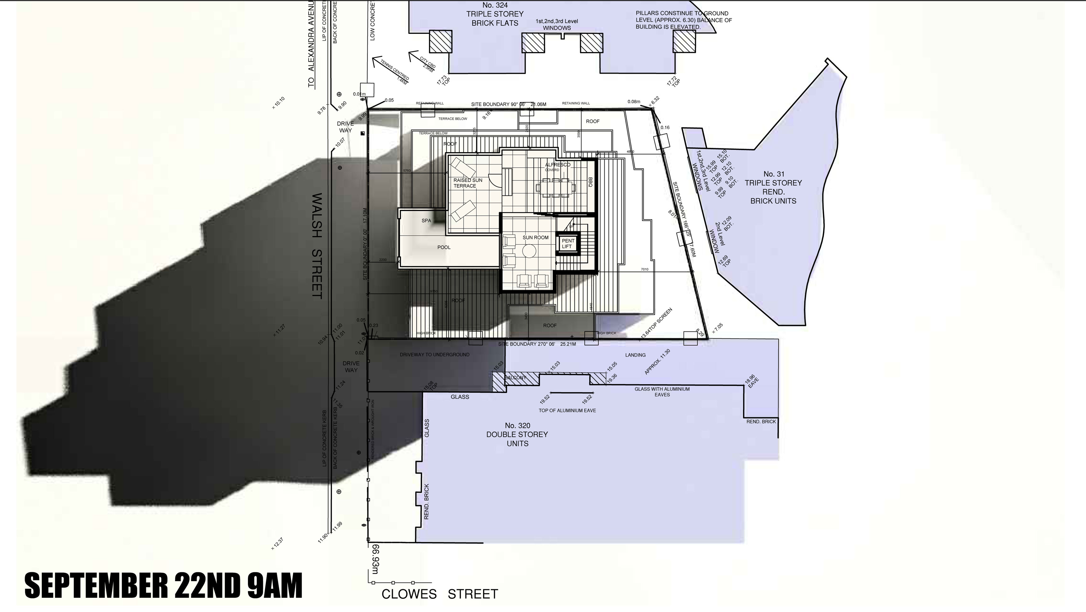
What is a Shadow Diagram?
Shadow Diagrams are 2D plans that show how the proposed building will cast shadows on the neighbouring properties. The times of day that are generally needed for Victoria are on the 22nd September at 9am, 12pm and 3pm although some applications require hours from 8am to 4pm.
In New South Wales the hours for 22nd June are generally what are required.
The above drawings are the basic drawings required for building a house. You can get more involved in the types of drawings you would like to include in your building drawings. These additional drawings are crucial if you want every part of the design to be built as desired. Below I will take you through to the different types of additional drawings you can provide to the builder.
What are Internal Elevations?
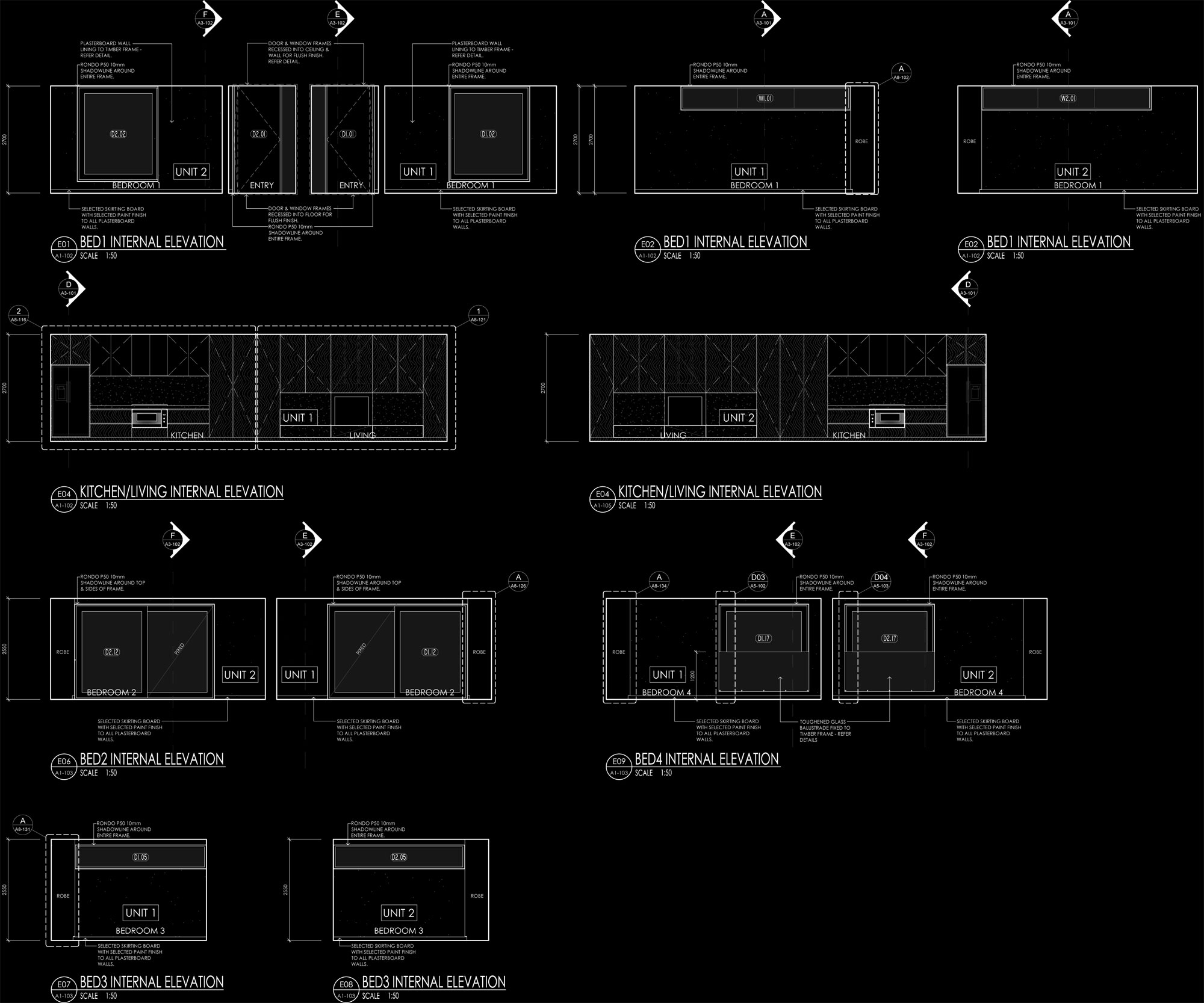
These elevations show what the building looks like from inside (interior).
They are typically at a scale of 1:50 (sometimes 1:100)
Internal Elevations show details on the interior of the building that cannot be seen from the basic drawings we looked at earlier. To know which wall you are looking at in the building, a reference symbol is placed on the floor plan drawings that references to the internal elevations. If you look back at the earlier floor plan drawing, you will see a symbol like the one below:

The arrow point is facing at the wall, the number E04 represents the Internal Elevation number, and the A7-201 is the drawing number that the Internal Elevation is on.
In the example drawing below, you will also notice other reference symbols to other drawings that will contain more detailed information about the internal elevations.
The section lines are also shown through the internal elevations to give clarity and a further reference to that area.
Here is an example of an Internal Elevation. (click for larger view) (Title Block ommitted)
Reflected Ceiling Plan
What is a Reflected Ceiling Plan?
These are like floor plans, except it is like you are laying on your back on the floor and looking towards the ceiling.
By doing this, information about how raised and lowered parts of a ceiling can be shown as well as heights, but often the main purpose of this type of plan is to show where light fixtures and switches are to be located.
They are typically at a scale of 1:100
Reflected Ceiling Plans should show light fixture locations and which switch they are wired to. The example below shows dashed lines that represent how the wire should be connected to the light switch. The text that says '2W' means this is a 2 way switch that can be turned on or off from 2 different swtiches. The rectangles with text in them such as CH 2700 means that the ceiling is 2700mm from the floor directly below it.
Here is an example of a Reflected Ceiling Plan. (click for larger view) (Title Block ommitted)

Power Plan
What is a Power Plan?
This is another type of electrical plan, except you are looking at the floor plan as you would typically from above, and the information is different from the Reflected Ceiling Plan. Power Plans show locations of electrical outlets, tv antenna points, telephone points, data points, switch board, meter box, inbuilt speaker and electrical hot water services etc.
They are typically at a scale of 1:100
Power Plans should indicate where a power outlet is to be located, its height above floor level and whether it is a double or single outlet. Other information may be that the outlet is going to be an external outlet or indicating what the exact purpose of the outlet is (e.g for a fridge, over, microwave etc.)
Here is an example of a Power Plan. (click for larger view) (Title Block ommitted)

Door and Window Schedule
What is a Door and Window Schedule?
This is a drawn specification of the Door and Window labels put on the floor plans and elevations. It shows the doors and windows in elevations.
They are typically at a scale of 1:50 (sometimes 1:20)
Information put on these drawings can vary but all door and windows must be labelled and numbered exactly as they have been on the floor plans and elevations so there is not confusion to which item is which.
Typically you will want to dimension the width and height of the doors and windows, show any glazed areas and mark them as clear or obscure glazing, show the frame thickness, show whether the window/door has louvres and nominate the material they are to made of. That is the basics information required. Certain door and window systems are also available as specific products that can be specified.
Here is an example of a Door and Window Schedule. (click for larger view) (Title Block ommitted)

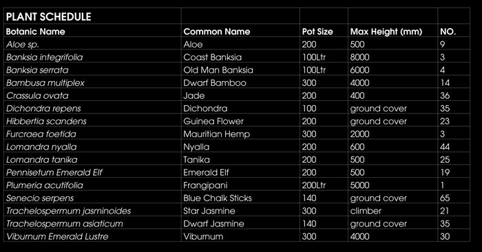
Landscape
These drawings shown where plants and trees are to be located, and what the species of each is. The landscape plan is usually overlayed on the building floor plan.

Joinery Drawings
What are Joinery Drawings?
These types of drawings show the desing intent of all joinery or cabinetry in the building. These drawings may be used to show how kitchens are to look, including placement of drawers, cupboards, benchtops and even the types of drawer closers and cupbaord handles. This also applies to bathrooms, laundries, built in robes, integrated entertainment units, studys etc.
The joinery drawings also show the material finishes to be applied to the joinery, benchtop, splashback etc.
They are typically at a scale of 1:20 or 1:50 and plotted at A3 size
Depending on the complexity of the Joinery you are drawing will depend on how many drawing sheets you will need. Kitchens typically need more information than most other joinery in the house.
The first drawing used to describe the design intention
of the Joinery is a floor plan. This isn't the whole house plan but just a close up of the area in question. For instance, kitchen joinery would show a plan of the kitchen only.
The floor plan showns the length and depth of joinery and benchtops, placement of sinks, taps, tubs etc. and also shows the joinery material finish.
Similar to the Internal Elevations, there is a symbol that is shown on the floor plan that indicates which part of the joinery you are looking towards as shown below:

The number 4 references this is the 4th Elevation, and the number below it references the page this Elevation is on
All elevations must have a unique reference number or letter.
The arrow point on the symbol is the direction of the elevation.
The joinery elevations show the height of the cabinetry, shelfs and also indicate the material finishes. Sometimes placement of the power outlets are shown too as well as ovens, dishwashers, washing machines, etc.
All drawings may have notation to clarify or specify details.
Here is an example of a Joinery drawing Floor Plan and Elevation. (click for larger view) (Title Block ommitted)


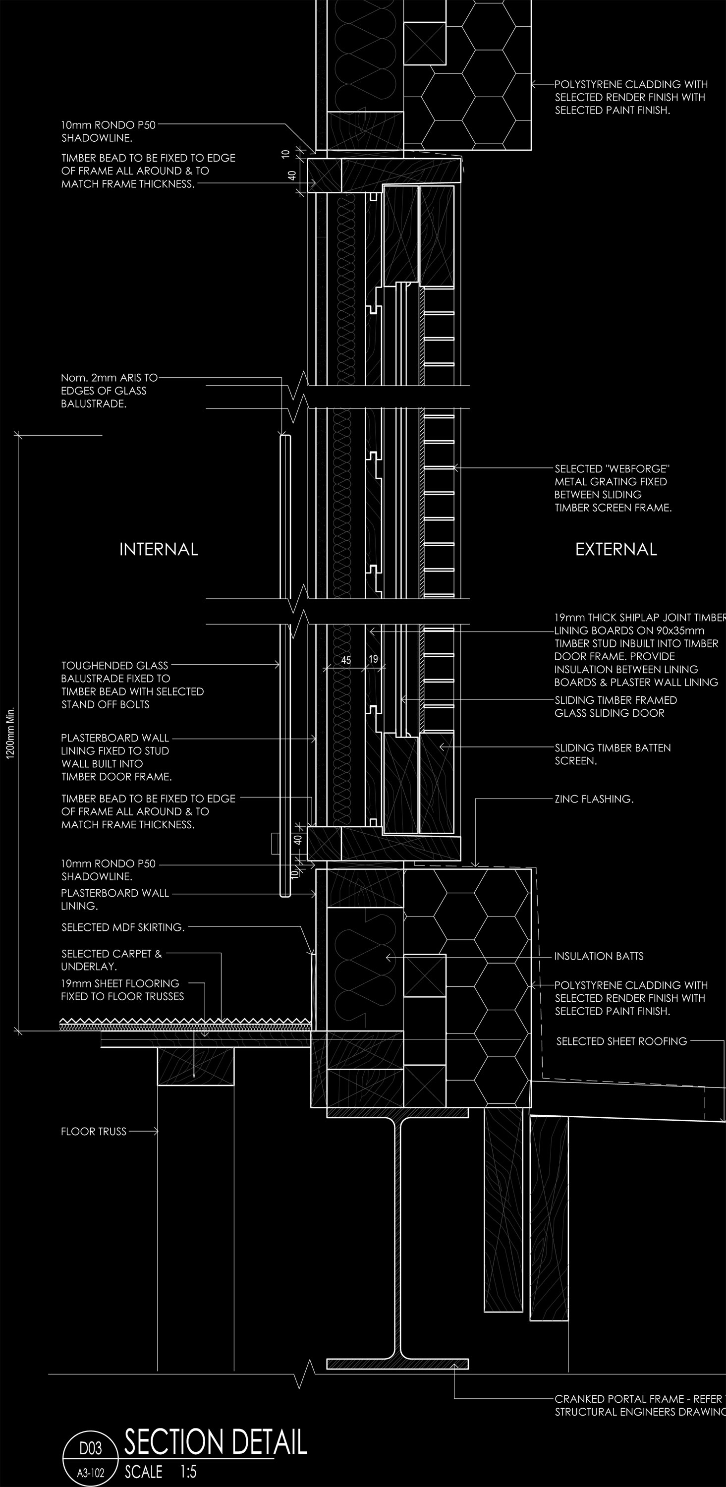
Details
What are Detail Drawings?
Sometimes standard floor plan or section drawings are at a scale where it is too hard to see what information is required to construct a building as it is intended. Even at a scale of 1:50 can be too small. This is where detail drawings come in. They are drawn at a larger scale so all 'details' can be clearly seen.
They are typically at a scale of 1:10 or 1:20 (sometimes 1:5)
Details are referenced from another drawing, be it a floor plan or section etc.
Details can be of just about anything inside a building so there are no specific rules to how they should be drawn except that they should be clearly drawn, notated well, be correctly drawn in regards to construction methods and be correctly referenced back the drawing where it was referenced from.
Here is are 2 examples of Details, one is a section detail, the other a plan detail. (click for larger view)
(Title Block ommitted)

In addition to the information I provide for designing and drafting your own house, I have another side project that tells you how long a house or land has been For Sale or Rent in Australia.
It is also Free to Use and also has a search to give you a price range indication of house and land
for sale that doesn't have a listed price.
It is called Get House Date www.gethousedate.com.au Mobile Friendly too.