 |
AUTOCAD CUSTOM TOOLBARS |
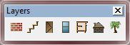
Fig.8
Toolbars are quite useful for accessing frequently used commands. Toolbars can be created in AutoCAD using 'drag & drop' features built inside of AutoCAD or by writing the code onto the menu (.mnu) file. I won't be discussing the 'drag & drop' method, but there is plenty of information on how to create Toolbars this way inside the AutoCAD help file. I often find it just as quick to type(code) in the toolbars to our menu (.mnu) file. Even if you prefer making your toolbars inside of AutoCAD, it is still good to understand what AutoCAD does to make the toolbars appear. If you create Toolbars inside of AutoCAD, the Toolbars are not included in the .mnu file, they are instead included in the .mns file. This is OK if you aren't going to reload your .mnu file, but if you do, AutoCAD overwrites the .mns file, and in the process, all of the toolbars you had created are overwritten (deleted).
Fig.8 Shows a quick Toolbar I created that makes a layer the current layer just by clicking one of the buttons. The images are fairly poor but they will do for this tutorial. I will only be creating a 2 button toolbar for the tutorial.
OK, lets get started. Open your menu file 'MyMenu.mnu'.
Similar to the ***Helpstrings section we first need to create a toolbar section ***Toolbars. So press enter a few times to make a bit of a break between the ending of the ***Helpstrings section and type ***Toolbars
Press enter key and now type below ***Toolbars - **MyMenu_Layers
What this is telling the AutoCAD, is that we are going to be creating a toolbar in the menu file called MyMenu & a toolbar called Layers. This isn't the toolbar itself, just a pre-cursor to tell AutoCAD to make way for a new toolbar. You should now have something similar to Fig.9. Note the _ (underscore) between MyMenu and Layers, this is required to seperate the menu file name from the toolbar name.
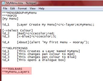
Fig.9
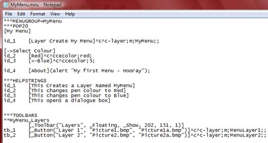
Fig.10
I am going to jump right in now, Fig.10 I have added all the other information needed to complete our toolbar. Don't feel overwhelmed, this is all very easy and follows the same type of format we used in earlier tutorials on creating menu commands.
Firstly I will explain the basic toolbar syntax of the AutoCAD toolbar below:
| [_Toolbar("_ToolbarName", orientation, visible, x-position, y-position, rows")] |
|---|
Our first line we will add after **MyMenu_Layers is the toolbar name as it will be seen in AutoCAD. We start with [_Toolbar - this is always called to tell AutoCAD this is the start of the toolbar. All toolbars start with this. You will notice the same brackets are used as in the menu names.
TOOLBAR NAME
We then call ("Layers", - this is the name of the toolbar titlebar (as seen in Fig.8). Notice the comma seperating the different sections of the line.
TOOLBAR ORIENTATION
After the toolbar name is _Floating, - this means when we load the toolbar in AutoCAD, it won't be docked to AutoCAD, but will be freely floating on the Model or Paperspace part of the AutoCAD screen. The location is based on co-ordinates we will specify further along the line.
Note the following options for the orientation of the toolbar can be: Floating, Top, Bottom, Left, Right .
TOOLBAR VISIBILTY
_Show, - means the toolbar is on. As you may be aware toolbars can be closed/hidden, this makes sure when we load the menu file later it will be displayed.
Note the following options for the visibility of the toolbar can be: Show, Hide
TOOLBAR LOCATION x,y CO-ORDINATE
Next are a 2 numbers seperated by commas - 202, 151, The numbers represent the location the toolbar will be located on the screen when the menu file is loaded into AutoCAD. These numbers describe the number of pixels the toolbar will located on the screen. The pixels are determined from Left to Right and Top to Bottom. In this case, the toolbar will be located 202pixels from the left and 151pixels from the top of the screen.
TOOLBAR ROWS
Last number of the line is 1)] This tells AutoCAD how many rows the toolbar should have. In this case 1 means the buttons will be placed side by side. If I was to enter 2, the buttons would be 1 above the other. We also close the line with ) & ] This is the toolbar declaration completed. Next onto the the buttons.
BUTTONS
i am only going to discuss the first button as the 2nd button works the same as the first. i am also only discussing simple buttons rather than flyout buttons. I will add another tutorial on that in the future.
Alright, your first button.
| tb_1 [_Button("Layer 1", "Picture1.bmp", "Picture1a.bmp")]^c^c-layer;m;MenuLayer1;; |
|---|
The first part tb_1 This is the same as the earler tutorial on Helpstrings. We can associate a description to toolbar buttons under the helpstring section.
TOOLBAR BUTTON
Similar to the toolbar line, we call a button [_Button - As simple as that!
BUTTON NAME
Next we name our first button. I have named it ("Layer1", It can be called anything you like but must not contain spaces. Use _ or - instead of spaces.
BUTTON IMAGE / PICTURE
Now we get to the fun bit, we can add our own bitmap to the toolbar. Noticea toolbar picture must be a .bmp filetype or referenced from a .dll file (more on that later). As you may notice, we call 2 bitmaps - "Picture1.bmp", "Picture1a.bmp")]. The first Picture is a 16x16pixel sized Bitmap image which is the standard AutoCAD button size. The next is 32x32pixel image. These images are usually the same picture but at different sizes / quality. You can call the images anything you like, but you must make sure the images are in one of your AutoCAD support folders or they won't displar on your toolbar.
BUTTON MACRO COMMAND
Similar to the menu macros we created earlier, we write a series of commands to be executed when the button is pressed.
In this case ^c^c - cancel current command, -layer;m;MenuLayer1;; - call layer command, make a layer called MenuLayer1 (if not created already) and make the layer current.
>>>>4. AutoCAD Slide Library