 |
AUTOCAD DYNAMIC BLOCK - DOOR Part 1 |
_Continuing on from Part 1 of creating a dynamic block, I will show you how to add a couple more actions to the door so it can be flipped.
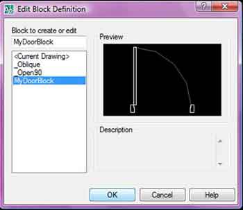
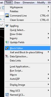
Open up your door from Part 1 of the tutorial. We want to go back into the Block Editor again. On the menu bar, go to TOOLS, then Click, Block Editor (Fig.1). A window will appear (Fig.2) with a list of Blocks to choose from. Select the block we just created called MyDoorBlock (or whatever you named it) and Click OK . We are now back in the block editor.
|
|
|---|
You should now be in the Block Editor again. Once in the block editor, left click 'Flip Parameter from the Tool Pallette (1 - Fig.3), then hold down (SHIFT KEY) then RIGHT mouse click to bring up menu. LEFT click 'Mid Between 2 points' on the menu (2 - Fig.3).
|
|
|---|---|
Now Left click the Midpoint of the door jamb (1 - Fig.4) then the other door Jamb Midpoint as shown (2 - Fig.4) If you move the mouse around now you will see a rubber band line. This line tells AutoCAD where to flip from. We want this line to be horizontal so Left click The midpoint on the door jamb again (2 - Fig.4). AutoCAD now asks to place the label for the Flip, left click near the centre of the door as shown Fig.5. |
|
Next click the 'Flip Action' from the Actions tab of the tool pallette (1 - Fig.6), then left click the 'Flip State' parameter we just created (2 - Fig.6). Next AutoCAD asks for objects to include in the Flip. Type 'all' at the command prompt then press 'Enter Key' twice. All objects have been included in the flip. Place the flip label as shown at 3 - Fig.6 If you exit the block editor now and click on the Flip arrow, AutoCAD will now flip the door in one direction. Next step is to flip the door objects in the other direction.
|
 Fig.6 |
Open up the Block Editor again if not already open.
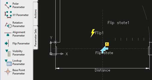
Once 'Node' selection is made, we can snap onto the node of the previous Flip parameter. Move your mouse over the flip parameter as shown then Left click the node when it is highlighted (1 - Fig.9) |
|
Next add a new Flip Action to the new flip parameter as done previously. If you were to now use your door, you may notice that when you strectch the door, the Flip arrows don't move. We want them to always be centered between the door jambs. To do this, we need to create a new Move Action. Left click Move action from the Tool Pallette (1 - Fig.11) then click the Distance parameter (2 - Fig.11). Next AutoCAD will prompt to place parameter point, Left click as shown at 3 - Fig.11. AutoCAD now asks to select objects to move. Select the 2 flip states as shown 4 - Fig.11. Place the Move label as shown 1 - Fig.12. |
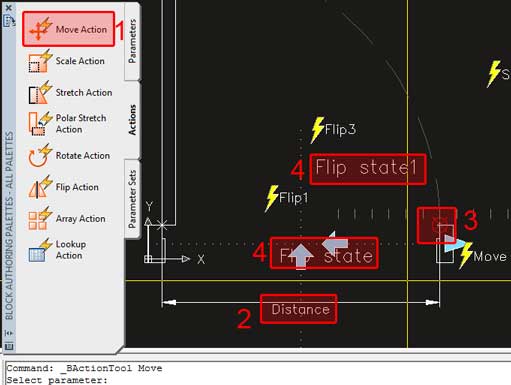 Fig.11 |
We still need to make 1 more adjustment. The move command at the moment won't move the flip states to the centre. We need to tell AutoCAD to only move half the distance of the Distance parameter. To do that, select the Move Parameter (1 - Fig.12), open up your properties window, scroll down to 'Distance Multiplier' and set it to 0.5 (2 - Fig.12) This will tell AutoCAD to move the flip states half the distance that the door is stretched to. Try it out. This concludes this tutorial on creating a Dynamic Door. Email with any questions or comments. |
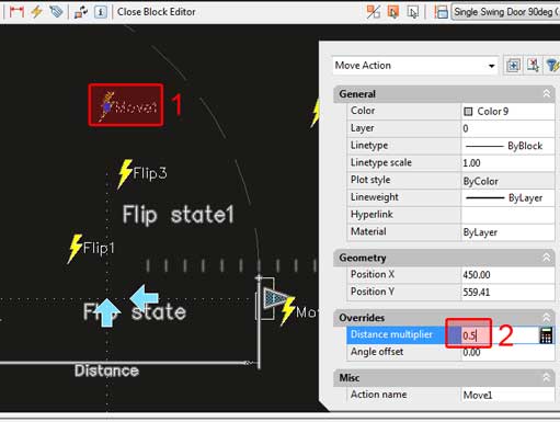 Fig.12 |


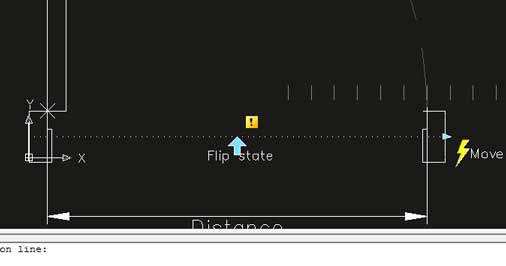
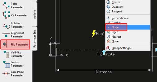 Fig.8
Fig.8 
comments powered by Disqus