 |
AUTOCAD DYNAMIC BLOCK - DOOR Part 1 |
_In this tutorial, I am going to show you how to make an AutoCAD Dynamic block of a door. The process is quite simple and hopefully will give you an understanding of how the process of making Dynamic blocks work
Firstly we need a door. Download a door I have already prepared here
Now open the drawing of the door in AutoCAD. (Fig.1)
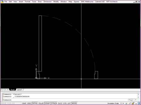
Fig.1
Next thing we need to do is make the door a block. We need to do this so we can edit the door in the block editor. The block editor is where we make this basic door block into a dynamic block.
To make the block, select all the objects that make up the door and type 'B' (for block). The block window opens (Fig.2).
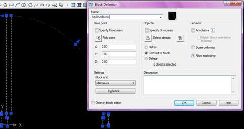
Fig.2
Name the block 'MyDoorBlock' (Fig.2), and Click OK.
Now the door is a block, so we can now edit it in the Block Editor.
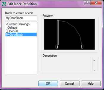
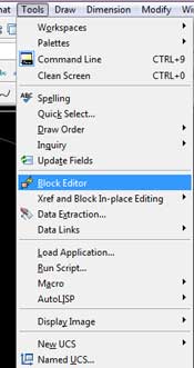
On the menu bar, go to TOOLS, then Click, Block Editor (Fig.3) A window will appear (Fig.4) with a list of Blocks to choose from. Select the block we just created called MyDoorBlock (or whatever you named it) and Click OK . We are now in the block editor.
|
|
|---|
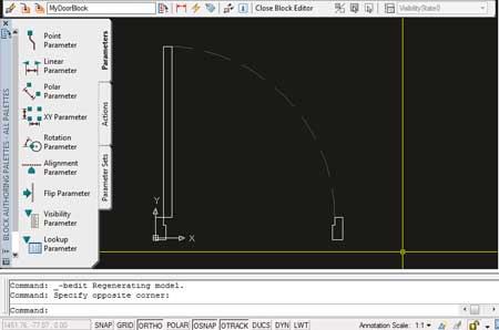
You should now be in the Block Editor. You should have a screen that looks similar to the image on the right (Fig.5) (Notice that my background is a grey/black colour - the default is a peach colour -you can change this in options) When you are in the Block Editor, there are new tools available to you. These tools can only be accessed whilst in the Block Editor. On the left hand side of the screen is the Block Editor toolbar pallette. First thing we are going to do is click the 'Linear Parameter' and add it to our door. |
|
||
|---|---|---|---|
After clicking Linear Parameter (1 - Fig.6), click First Point (2 - Fig.6) then Click Second Point
|
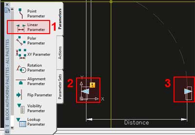 Fig.6 |
||
The linear paramater has 2 Arrow Grips. We only want 1 Arrow Grip so the door will have a fixed point at Arrow Grip 1, and be stretched by selecting and moving Arrow Grip 2. To do this, select the linear parameter by clicking on the word "Distance" (1 - Fig.7), then right click. A menu will pop-up. Move your mouse to 'Grip Display' (2 - Fig.7) on the menu, then Left Click on the number 1 (3 - Fig.7). You should now notice that there is only 1 grip on the linear parameter. If we had kept 2 Arrow Grips, the door would have been able to be modified in 2 directions. |
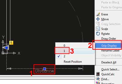 Fig.7 |
||
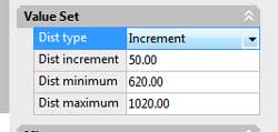
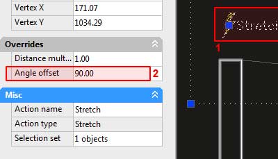
Before we add an action, we will alter one last thing on the linear parameter. (Note that actions can be added or delted at any time, there is no order things must be done) Again,select the linear parameter by clicking the word 'Distance'. Right click to bring up a menu, then Left Click on properties. The properties window will appear (if not already open) Scroll down the menu to "Value Set" (Fig.8) |
|
||
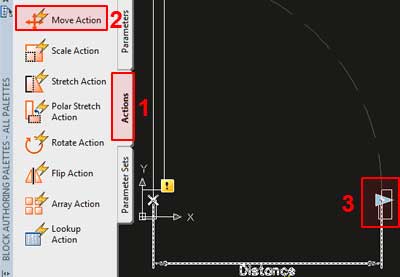
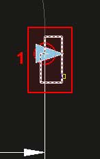
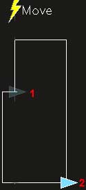
OK, so finally we will add an Action to the door. On the Toolpallete, select the Tab named Actions Move your mouse over Arrow Grip 2
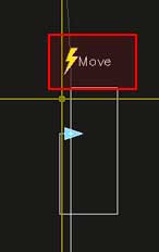
so a red circle appears near the Grip (3 - Fig.10), then click on/or near the Arrow Grip. You are asked to place the Action somewhere, place it just above the Arrow Grip (Fig.12) |
|
||
Alright, back in the Block Editor we are going to Stretch the Door Leaf based on the Arrow Grip position. After creating the rectangle, Select the door leaf then press enter. Locate the Stretch command just above the Door. Now this might seem all good and well but if you were to try out the door at this time it wouldn't behave correctly. The reason this is, is because the Stretch command by default will try and strectch Left & Right, not Up and Down. |
|
||
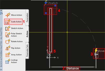
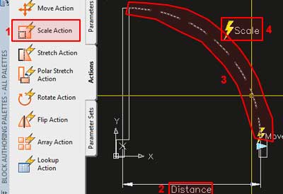
Similar to the previous 2 Actions, we go to the Actions tab on the Tool Pallete, but now we select Scale as our Action. After selecting Scale Action (1-Fig.15), select the word 'Distance' (2 - Fig.15) Then Select the Door Swing (3 - Fig.15) and position the Scale Action just above the Door Swing (4 - Fig.15). Close the Block Editor, Click Yes to Save changes and you now have a functioning dynamic door. One last thing, you may have noticed that the Arrow Grip isn't positioned in a very good place for stretching the door. It would be much better if the Arrow Grip was at the end of the Frame. Well, open the Block Editor once again and select the Arrow Grip (1 - Fig.16). Hopefully this gave you a beginning insight into creating a dynamic door. Next tutorial I will show you how to add additonal Actions to the door to make it flip directions by clicking on special grips. |
|

comments powered by Disqus