 |
AUTOCAD - DRAW A SITE TITLE BOUNDARY |
There is much confusion on how to draw a Site Title Boundary in AutoCAD. Hopefully this Tutorial will give you the knowledge to understand on how to draw a title boundary in AutoCAD.
The image below (Fig.1) is of the Title Boundary we will be using. I have used metres as the unit of measurement although the process is the same for any unit of measurement.
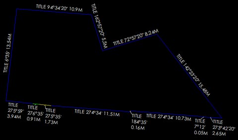
Fig.1
Open AutoCAD and start a new drawing. First thing we need to look at is in the Units dialogue of the drawing. This must be set correctly so when we enter the title dimensions and bearings into AutoCAD, we will produce the correct result.
At the command prompt, type 'units' or 'un' for short without the apostrophe (i.e ')
1 - Make sure you set the units for the measurement type you will be working with. This is not crucial as you can always re-scale a drawing to suit the correct or preferred unit of measurement. 2 - Tick the clockwise button. This tells AutoCAD to draw the lines of the Title Boundary in a clockwise direction which is what we want to do. 3. Click the Direction button. A new window will appear. 4. In the new window (Direction Control) select North. Click OK to close the window, and click OK again to Close the Drawing Units window. We are now ready to start drawing our Title Boundary. |
|
|---|
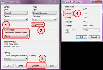 Fig.2
Fig.2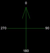
Starting at the lower left corner of the Fig.1 & shown in Fig.4, we will enter the co-ordinates of the Boundary. |
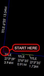 Fig.4 |
|---|
Ok, let's draw this line. Type 'L' for line and click a starting position in your new drawing (anywhere is OK)
Now we will enter the length and angle of this side. To do so, AutoCAD has a certain format to enter this information.
To enter the information for this line we type at the command prompt:
@13.5<6d35'
Notice we start with the @ symbol. This is basically saying from where the last point in the line command selected is, finish the next point @ <enter co-ordintes here>. You at present have only picked a random place in the AutoCAD model space. So this @ symbol is saying finish or goto the next specified co-ordinate from the point you picked.
Next we tell AutoCAD the length or distance to travel. In our case it's 13.5 metres, so we enter 13.5 (or 13,500mm)
The next symbol is the less than sign. This comes directly after the length. It is basically saying draw a line at specified distance (13.5m) at this angle.
The last section of the line describes the angle of the line. Notice the first part is 6°. Instaed of using the degrees symbol we simply type the letter 'd' meaning degrees. Next is the minutes which is a number followed by the minutes symbol ' which is an apostrophe.
We don't have seconds but if we did, the seconds symbol is " a quotation mark. Once you have typed in the co-ordinates hit enter. The line is now drawn in the correct angle and length.
The next side of the Title Boundary is 94°34'20" 10.9M. This would be typed at the command prompt as:
@10.9<94d34'20" then press enter
Our next line is drawn. This should give you an understanding of how to draw the title boundary. You can continue following the Title Boundary of Fig.1 all the way around for practice. Hope this was helpful, any questions or comments welcome.
The actural drawing file can be downloaded here